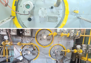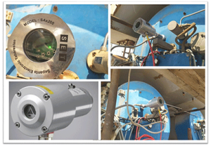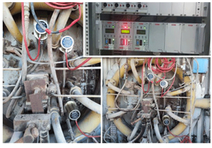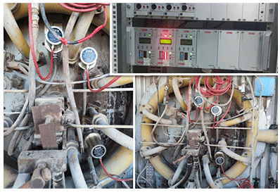

AGD01 Series, Installation And Application Guide
The Flame sensor AGD01 series monitors and analyses the flame features via the pulse signal of the connected sensor unit. The easy-to-read LCD display continually shows information on the defined setting and operational status. The flame intensity is presented at a current output 0.4…20mA for further analysis. There are three types of monitor units can connect to AGD01 sensor unit AGD01-Tix, AGD01-Tiy, AGD01-DU . Parameters of the monitor unit can be transmitted to a PC via a an Isolated RS232 interface. In this Article, we will explain how to set up the sensor and monitoring unit and how to interpret what the LCD displays. Moreover, by the following link , you can visit all products and type of flame scanner produced by Sepanta electronic Tabarestan.
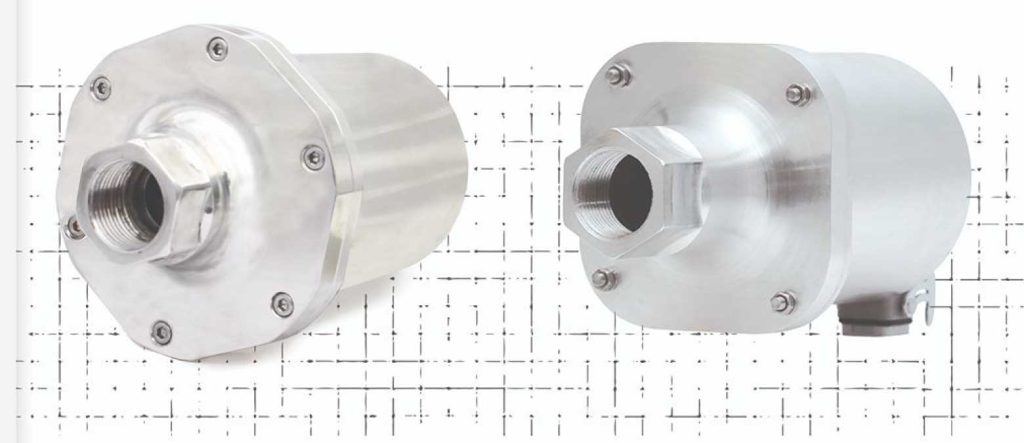

Fig 1) Flame sensor and monitor unit
AGD01 Flame Scanning System Components
AGD01 comprises of two units (Fig 2):
- Flame sensor unit
- Flame monitor unit
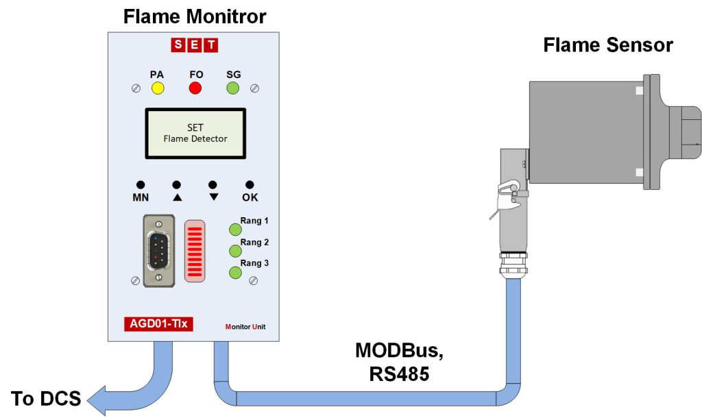
Fig 2) Flame sensor and monitor unit
The sensor receives the optical waves emitted from the flame through a side glass in the combustion chamber, and converts it to the electrical signal by a opto-detector. Then, the signal received from the opto-detector is analyzed in the digital processor and the features of the flame quality are extracted. The flame quality features are sent to the flame card via a RS485 network. The system is capable of operating in severe temperature conditions such as 85 ° C
AGD01 Advantages
- The digital scanner is capable of recognizing the percentage of optical spectrum, i.e. how much of the received spectrum from the flame is UV and how much is IR. With this feature, it is possible to measure the flame quality inside the combustion chamber and compare it with an ideal flame.
- The ability to detect the flame intensity inside the combustion chamber.
- The digital scanner has a special software that can detect flame status and check it by connecting to the monitoring card (fig.7).
- Temperature recording inside the scanner in the long run allows to check the temperature inside the scanner. Thus, the issues of the side glass cracking and hot air leakage can easily be detected by checking the scanner temperature.
- Digital data transfer in physical layer of RS485 and Modbus protocol. This method of transferring data is immune to the environmental noise, and the destructive effects of disturbing signals is very low.
Table 1) Optical spectrum of the flame sensor and its application
|
Feature |
Suitable for fuels |
Spectrum |
Part Number |
||||
|
GAS |
OIL |
COAL |
WOOD |
H2S |
|||
|
Highly sensitive and selective monitoring of gas and oil flames |
•• |
• |
Narrowband UV |
AGD01-S18C |
|||
|
Selective monitoring of a single burner of oil and gas flames in multi burners chamber with low NOx combustion ideally suited for Multi-Flame Burner |
• |
•• |
• |
UV |
AGD01-S22C |
||
|
combustion chamber flame monitoring (coal, oil) |
• |
• |
•• |
• |
Visible |
AGD01-S23C |
|
|
combustion chamber flame monitoring, Ideal for monitoring oil burners which have insufficient UV radiation caused by NOx reducing methods ideally suited for Gas Turbine |
•• |
• |
• |
•• |
IR |
AGD01-S21C |
|
UV Flame Scanner AGD01-S18C
AGD01-S18C is our UV flame scanner best suitable for UV spectrum detection in multi-burner furnaces and boilers. But since it uses a UV lamp, it requires a higher level of maintenance. UV lamps lose intensity over time. Therefore, most systems specify a replacement interval often every 12–24 months for industrial, depending on lamp Track lamp life and keep a replacement schedule.
UV Flame Scanner AGD01-S22C
AGD01-S22C is our UV flame scanner best suitable for UV spectrum detection in multi-burner furnaces and boilers, using UV photo diode sensor.
IR Flame Scanner AGD01-S21C
AGD01-S21C is our IR flame scanner best suitable for visible spectrum detection in single-burner furnaces and boilers, using visible photo diode sensor. When flame detection is critical and flame intensity is so low, we recommend the S21C series
visible Flame Scanner AGD01-S23C
AGD01-S23C is our flame scanner best suitable for visible spectrum detection in coil and oil burners, using IR photo diode sensor. Where accuracy and durability are critical, we recommend the S23C series.
These three features of the flame are easily extracted by the digital processor. However, as mentioned earlier, to prevent any environmental optical disturbances, measuring the flame flickering intensity is the best method for detecting flame status.
Input / Output Signals Of The Sensor Unite
The electrical connection of the sensor unite and flame analysis card is carried out by a 5-string cable. Two strings are for 24V voltage supply from the analysis card to the flame detection unite. Three strings are for RS485 serial connection physical platform. ModBus protocol is used for making connection in RS485 physical platform. In the system, analysis card and sensor are configured as master and slave, respectively. In order to minimize circuit noise in this string cable, the earth wire of power supply unit is separated from the RS485 ground (Fig 6).
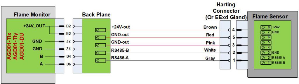
Fig 3) Cable connection of the flame detector.
.The flame analysis card has a major terminal and a peripheral terminal for RS232 serial connection
Input/output signals in the major terminal of the flame card are shown in Fig 7. Input/output signals of the sensor are shown in Fig 8.The data in Table 3 is provided in the central control room with RS232 protocol for the user.
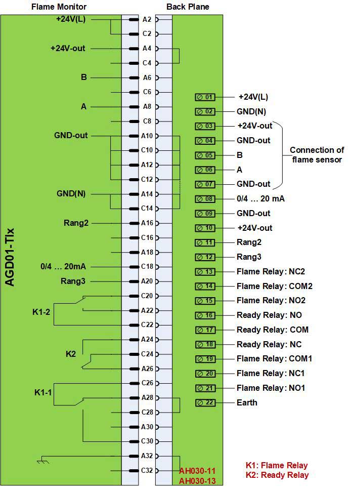
Fig 4) The output major terminal in the monitor Unit.
Also, by the Flame Scanner Explorer software, the data can be observed directly (Fig 9).
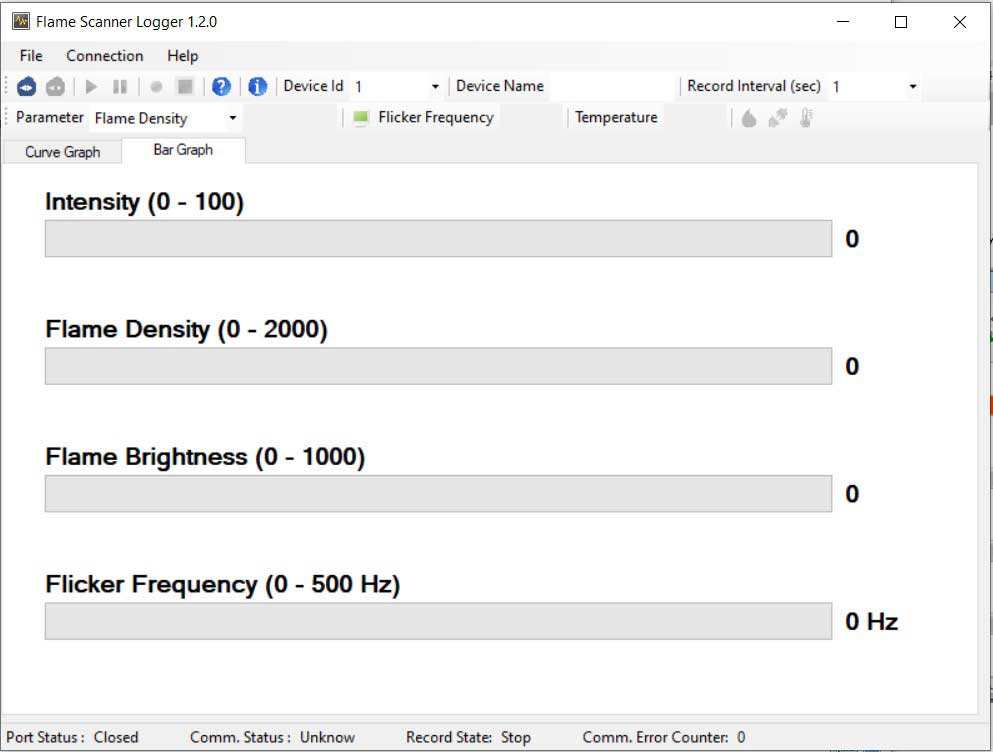
Fig 5) The main page of Flame Scanner Explorer software.