About Compact Flame Scanner SAx-200

Compact Flame Scanner SAx200, along with other models of flame scanners, is designed to detect the existence of  flame inside the combustion chamber, and aims at preventing fuel injection into the combustion chamber in the absence of flame formation (Fig 1). If the flame goes out, the system protection will operate in one second and issue the fuel valve closing command. This action prevents from fuel accumulation in the combustion chamber and possible explosion. In this article, we will describe the performance of this model of flame scanning system. you can find more about SAx-200. You can find more about the SAx-200 and download the datasheet on our product page.

Fig. 1- SAx-200


SAx-200

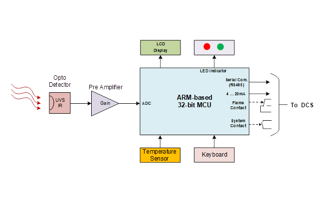
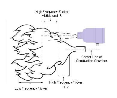
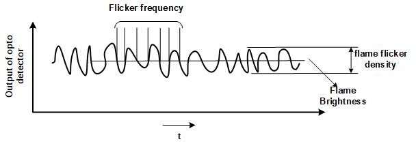
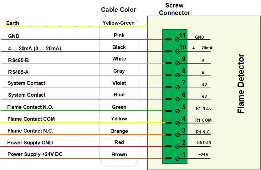
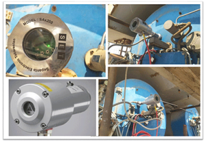
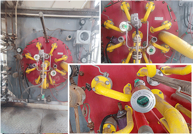
SAx-200 is a compact Flame detection system, in Fig 2. The sensor receives the optical waves emitted from the flame through a side glass in the combustion chamber, and converts it to the electrical signal by a opto-detector. Then, the signal received from the opto-detector is analyzed in the digital processor and the features of the flame quality are extracted. The flame quality features are sent to the control room via a RS485 network, 4 … 20mA hardwire and a dry contact. The system is capable of operating in severe temperature conditions such as 70 ° C.

sax-200 flame scanner schematic

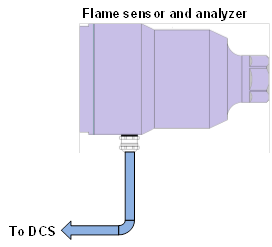
Fig.2 SAx-200 schematic

SAx200  Advantages

A digital 32-bit ARM family processor is used in SAx200  (Fig 3). In addition to performing the main task of Flame monitoring, this processor also offers the following new features:

SAx-200 flame scanner block diagram
Fig. 3- SAx-200 block diagram
  • The digital scanner is capable of recognizing the percentage of optical spectrum, i.e. how much of the received spectrum from the flame is UV and how much is IR. With this feature, it is possible to measure the flame quality inside the combustion chamber and compare it with an ideal flame.
  • The ability to detect the flame intensity inside the combustion chamber.
  • The digital scanner has a special software that can detect flame status and check it by connecting to the monitoring card (fig.7).
  • Temperature recording inside the scanner in the long run allows to check the temperature inside the scanner. Thus, the issues of the side glass cracking and hot air leakage can easily be detected by checking the scanner temperature.
  • Digital data transfer in physical layer of RS485 and Modbus protocol. This method of transferring data is immune to the environmental noise, and the destructive effects of disturbing signals is very low.
  • Opto-detector

    One of the methods for detecting flames is using opto-detectorBy receiving light, opto-detectors generate electrical signals. The higher the light intensity, the larger the amplitude of the signal output of this sensor. Thus, it is easy to distantly detect the flame using this type of sensor.

    The biggest problems in applying opto-detectors for detecting flame are the disturbances caused by background light and also, sensor’s behavior changes along with the temperature. Radiation of infrared rays from hot objects is easily measured by opto-detectors. This optical spectrum is also emitted from hot objects in the absence of a flame, which easily leads to a false decision regarding the existence or absence of the flame. The background light caused by sunlight, tungsten bulbs and fluorescent lamps also complicates the flame detection. Though, due to the closed gas turbine, the environmental lighting is not very effective. Anyway, to prevent these disturbances, the best method for detecting flames is measuring the flame’s periodical and instantaneous variations. This feature is known as flame flickering. Figure3 shows the flame on the output of a burner.

Flame flickering at a burner
Fig 4) Flame flickering at a burner.

The flame can usually be divided into three regions at the burner output. The region close to the fuel output, which its optical spectrum is often in the UV range, and flame flickering frequency is high. If the turbine fuel is diesel or mazut, the intensity of this spectrum is reduced and the optical spectrum goes to the visible area. The optical spectrum of the middle region of the flame is visible and infrared light with a high flickering frequency. The third region is the flame end, whose optical spectrum is slightly in the visible area and more in the infrared region. The flickering frequency of the flame light is low in this region.

Since different fuels such as natural gas, diesel or gasoline might be used in gas turbines, most flame detection systems are concentrated on flickering of the mid-flame region. This region is similar in most fuels; therefore, most of the flame sensors are for visible and infrared light.

Three types of opto-detector are used in SAx100. These opto-detectors covers optical spectrum from 230 to 2600 nm for different applications (Table 1).

Table 1) Spectrum of opto-detectors

FeatureSpectrum Feature
combustion chamber flame monitoring, Ideal for monitoring oil burners which have insufficient UV radiation caused by NOx reducing methods.900nm to 2600nmS21C
Selective monitoring of a single burner of oil and gas flames in multi burners chamber with low NOx combustion190nm to 500 nmS22C
combustion chamber flame monitoring (coal, oil)230nm to 1100nm

S23C

Flame characteristics

A sample of the flame opto-detector output signal is shown in Fig 5. Features that could be extracted from this signal include flame intensity, flame flickering intensity, and flame flickering frequency.

The flame brightness is the average value of the sensor output signal.

The flame flickering density is the alternating amplitude of the sensor output signal.

The flame flickering frequency is the frequency of the alternating signal of the sensor output.

Intensity, amplitude, and frequency of the flame flicker
Fig 5) Intensity, amplitude, and frequency of the flame flicker

These three features of the flame are easily extracted by the digital processor. However, as mentioned earlier, to prevent any environmental optical disturbances, measuring the flame flickering intensity is the best method for detecting flame status.

Input / Output Signals

The electrical connection of the flame sensor and flame analysis card is carried out by a 12-string cable. Two strings are for 24V voltage supply from the analysis card to the sensor. Three strings are for RS485 serial connection physical platform. ModBus protocol is used for making connection in RS485 physical platform. In order to minimize circuit noise in this string cable, the power supply unit is isolated from the RS485 (Fig 6).

Cable connection of the flame detector
Fig 6) Cable connection of the flame detector


Output data from the detector includes flame features which is sent to control room by the serial line. The data is displayed in Table 2.

Table 2) Data sent from Flame Detector via RS485 network.

Range

data

0 … 1000

Flame Density

0 … 1000

Flame Brightness

0 … 100

Flame  Intensity

0 … 500Hz

Flame flickering frequency

-20 … +100oC

Sensor temperature

Well/damaged

Flame sensor state

ON/OFF

Flame State

Also, by the Flame Scanner Explorer software, the data can be observed directly (Fig 7).

The main page of Flame Scanner Explorer software
Fig 7) The main page of Flame Scanner Explorer software

Guidelines for observation and adjustment of the analysis card

As mentioned earlier, digital flame detector has many potentialities. This potentiality can be observed and adjusted in the flame monitor pages. The flame monitor page and its components are brought in Fig 8.

The flame monitor page components include:

  1. System Good indicator LED (SG)
  2. Flame OK indicator LED (FO)
  3. LCD Display
  4. Menu switch
  5. upper switch (˄)
  6. Lower switch (˅)
  7. OK switch

System Good indicator LED (SG)

If this LED is constantly on, it means there is no fault in device performance. If this LED is flashing, it means there is one or more fault conditions in the device performance. In the case of an error, the corresponding error can be observed on the error display page. Errors include no connection of flame sensor or a temperature higher than 70 degrees Celsius.

Flame ON indicator LED (FO)

When this LED is on, it means the existence of a flame which its flickering intensity is greater than the amount of flame-on declaration point, which is adjustable by the user. When this LED is off means the lack of proper flame.

LCD Display

This display is used to view the device status and flame details as well as the regulatory values.

Menu switch

Menu switch is for entry to setting section and back to display section. 

Upper and lower switches

Upper (˄) and lower (˅) switches are for increasing and/or reducing adjustable parameters and also, for observing display pages.

OK switch

Ok switch is for setting confirmation and storage.

RS485 Serial port

A serial port for online monitoring of values on a computer by the device. The base sequence of this port is identified in Table 2. The connection layer of this port is RS485 and connection protocol is MODBUS RTU. The serial connection features is 19200,E,8,1.

Display of the flame status and details

The device status and flame details would be shown in eight pages. With upper and lower switches, each of these pages can be selected and viewed. These pages include:

1.Flame Density

flame density

2.Flame Decreased Density

3.Flame Brightness

flame brightness

4.Flame flickering frequency

5.Flame Intensity percentage

6.Flame sensor temperature

7.Internal Offset Level

8.Self Check Density

9.Device Error

Device Error

10.The number of sensor connection errors with the device

11.Gain Range

12.Display Firmware Version

Display Firmware Version

13.Sensor Unite Firmware Version

Sensor Firmware Version

Suggested Posts